.jpg)
 Braking Resistors-2
 Braking Resistors-2
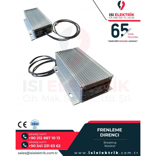
Load and Braking Resistors


.jpg)
Load and braking resistors are specialized electrical solutions used to manage energy in a controlled way within industrial power and motion systems. A load resistor applies a measurable and controllable electrical load to a power source, while a braking resistor absorbs regenerative energy during deceleration in drive-controlled motor systems and dissipates it as heat. For that reason, these products should never be treated as simple passive components only. They are part of a broader engineering decision involving power management, drive protection, process stability, commissioning, validation, and operational safety. Official technical sources describe load banks as controlled devices that apply load to generators, UPS systems, batteries, and other power sources, while braking resistor systems are used to dissipate excess DC link energy during rapid deceleration.
In industrial practice, these solutions are used in motor drive systems, hoists, cranes, elevators, conveyors, winding and unwinding lines, generator test platforms, UPS validation systems, battery discharge setups, and power electronics test environments. If the selection is poor, the result may be overheating, insufficient braking, unstable test conditions, nuisance drive trips, or shortened equipment life. That is why proper selection should not be based on resistance value alone. It must be evaluated together with power, voltage, duty cycle, cooling method, installation environment, and application profile.
What Are Load and Braking Resistors?
A load resistor is used to place a controlled electrical demand on a power source so that the source can be tested under predictable and repeatable conditions. In technical terms, the system converts electrical energy into heat and allows engineers to measure how the power source behaves under load. Load bank logic is valuable because it replaces a dispersed, unpredictable, and variable real-life load with a contained, organized, and fully controllable test load. That makes it highly useful for factory testing, field commissioning, maintenance procedures, and acceptance verification.
A braking resistor, by contrast, is mainly associated with variable speed drives and motor deceleration. When a motor slows down quickly, mechanical energy is converted back into electrical energy and returned to the DC link. If the system is not designed to feed that energy back to the supply, a brake chopper connects the braking resistor and the excess energy is dissipated as heat. This keeps the DC bus voltage from rising to unsafe levels and helps maintain controlled braking performance. ABB describes this operating principle directly in its drive braking documentation.
How the Operating Principle Works
In a load resistor application, the purpose is to draw controlled power from the source. A generator, UPS, inverter, or battery system may need to be tested before handover or after maintenance. In that case, the resistor assembly creates a defined load, either in steps or through controlled modulation. The absorbed energy is converted into heat and then removed through air-cooled or liquid-cooled arrangements. This allows the engineer to verify voltage stability, endurance, thermal behavior, and performance under realistic operating conditions.
In a braking resistor application, the system absorbs regenerated energy rather than drawing fresh input power. ABB explains that during rapid deceleration the motor generates extra energy, the DC link voltage rises, and the brake chopper connects the resistor whenever the voltage exceeds its operating threshold. The resistor then dissipates the energy as heat until the voltage returns below the limit. This is especially important in applications with fast stopping, frequent deceleration, high-inertia machinery, or tightly controlled stopping behavior.
Technical Construction and Design Options
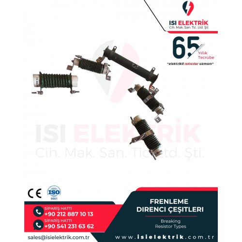
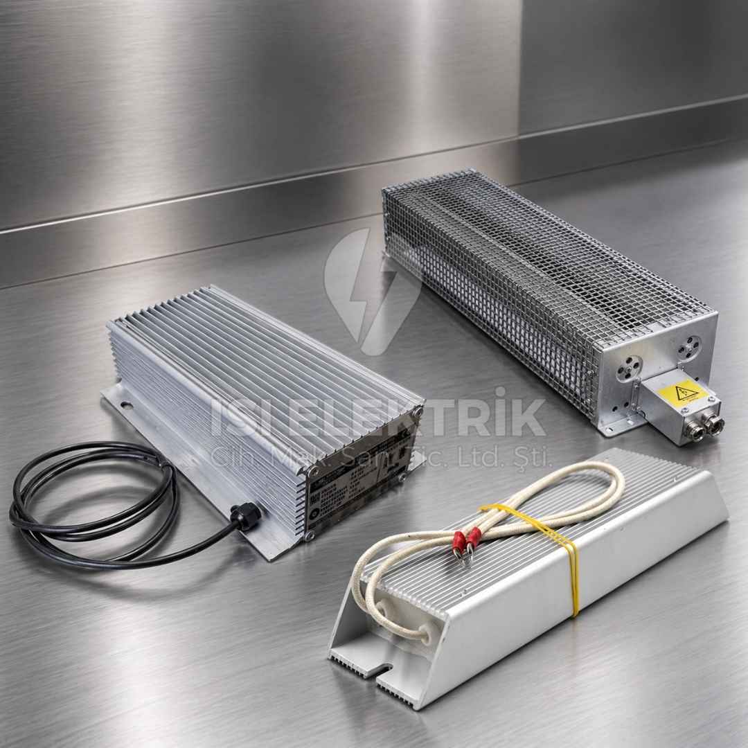
Load and braking resistor assemblies are not single-format products. Depending on the application, they may be designed as open-frame resistor groups, enclosed cabinet systems, air-cooled packages, liquid-cooled systems, compact modules, radiator-mounted solutions, or large containerized high-capacity banks. Official load bank sources show that the market includes everything from portable units to multi-megawatt containerized systems, and that test scenarios may require resistive, inductive, capacitive, or combined load characteristics.
Material selection is equally important. Depending on design intent, the assembly may use corrosion-resistant alloys, stainless hardware, ceramic insulators, steel enclosures, high-temperature supports, and engineered airflow structures. Load bank manufacturers highlight chromium alloy resistor elements, ceramic support structures, and stainless steel details for durability and reliability. On the braking side, however, the critical issue is not just the resistor material itself but the overall thermal behavior, contact protection, cable insulation, overload protection, and mounting safety.
Dimensions, Form Factors, and Electrical Ratings
In this product family, diameter, length, thickness, cabinet size, terminal layout, and overall form vary entirely by application. Some solutions are wound or grid-based, some are rack-mounted modules, and others are cabinet-integrated custom assemblies. In higher-capacity systems, airflow path, fan direction, hot air discharge, structural frame, cable entry, and maintenance access all become part of the dimensional design. That means size selection should not be reduced to physical fit alone. It should be planned together with heat dissipation, airflow, service access, and safe touch protection.
Resistance, power, voltage, and temperature are the key technical parameters, but there is no universal standard value. Manufacturer documents typically specify resistance value, continuous power, short-time power, maximum current, DC operating voltage, protection level, and duty cycle together. For example, one Siemens braking resistor model is listed with 50 kW rated power, 200 kW short-time power, 3.1 ohms, and 670 to 810 V DC. This is useful as an industry example, but it should never be treated as a general rule. On the load bank side, official sources show multiple voltage and capacity combinations such as 400 V, 415 V, 480 V, and capacities reaching hundreds of kilowatts or more. Real system data must always drive the final selection.
Temperature Resistance and Thermal Management
Thermal management is at the center of load and braking resistor engineering because the core function of the product is to convert electrical energy into heat. ABB documentation states that braking resistor surface temperature can be very high and that air flowing from the resistor can reach hundreds of degrees Celsius. Siemens documentation also warns about hot surfaces, burn risks, fire risks caused by incorrect mounting, and overheating caused by inadequate installation. In other words, selection must be correct not only electrically but also from a thermal safety perspective.
In practice this means proper ventilation, non-flammable surroundings, cabinet airflow design, fan-assisted or liquid-cooled selection, hot air discharge direction, touch protection, and thermal switch integration. In some applications, air cooling is sufficient. In others, especially where space is limited or power density is high, liquid-cooled load bank solutions may offer operational advantages. The cooling approach directly affects both service life and safety.
Applications and Industrial Use Cases
Braking resistor solutions are widely used in cranes, hoists, elevators, conveyors, extrusion lines, winding systems, high-inertia fans, test rigs, and drive systems that require controlled stopping. They become especially important where rapid deceleration, repeated stop-start cycles, or heavy moving masses are involved. Load resistor systems, on the other hand, are commonly used by generator manufacturers, field service teams, UPS infrastructures, battery and inverter test systems, standby power commissioning projects, and validation environments. Official sources specifically mention generators, battery systems, UPS systems, inverters, wind generators, and hydro generators among common applications for load bank testing.
Considering the broad industrial profile served by Isı Elektrik Rezistans, this product family can support engineering needs across automotive, glass processing, tempering furnaces, defense, food, medical, chemicals, textiles, aviation, metal and machinery, plastics, injection systems, extrusion, thermoforming, and many other process environments. In many of these fields, the need is either to create a controlled electrical test load or to manage deceleration energy safely. The real engineering value lies in accurately defining the application, not in treating the product name as a one-size-fits-all category.
How to Select Power and Voltage
Proper power and voltage selection begins by defining exactly what the product is expected to do. Is it intended to test a generator, or to absorb regenerative energy from a motor drive? In braking applications, the key inputs include motor power, inertia, deceleration time, braking frequency, DC bus conditions, ambient temperature, and duty cycle. In load applications, engineers focus on source rating, voltage level, phase configuration, target power factor, test duration, load steps, and cooling method. Official technical guidance consistently emphasizes that both braking resistor selection and load bank selection must match the real system capacity and voltage range.
One of the most common mistakes is to use oversimplified matching logic such as selecting only by motor rating or only by generator nameplate capacity. In reality, the design must also consider peak power, average thermal load, repeat cycle, ambient temperature, airflow rate, and maximum surface temperature. Braking applications often involve short-term high-energy pulses, while load bank applications may require long-duration continuous testing. Those differences change the entire design approach.
Why Duty Cycle and Proper Sizing Matter
Duty cycle is one of the most important parameters, especially for braking resistor assemblies. ABB states that brake chopper and resistor solutions are typically dimensioned for a specific braking cycle and that longer braking periods require more accurate sizing. In other words, selection cannot be based on resistance alone. The engineer must determine how long, how often, and under what cycle the resistor will absorb energy. Siemens documentation also indicates that the application duty profile must be compared to standard duty cycle references.
A system that brakes briefly but frequently is not equivalent to one that brakes rarely but for a long duration. Likewise, where regenerative energy is high and continuously repeated, official guidance indicates that other solutions, including regenerative drive approaches, may be more suitable. Proper sizing therefore affects not only performance but also safety, reliability, and total lifecycle cost.
Installation and Integration Considerations
The most critical installation topics are mechanical mounting, protection from hot surfaces, cable routing, grounding, thermal monitoring, ventilation clearance, and fire safety. Siemens warns that incorrectly mounted braking resistors can overheat, must be kept clear of combustible objects, and must not have objects placed on or above them. ABB similarly requires protection against accidental contact, adequate cooling, non-flammable surroundings, and thermal switch integration that can disable the chopper or shut down the drive in an overtemperature condition.
On the integration side, cable cross-section, cable length, shielding, EMI behavior, drive parameterization, digital input logic, and thermal feedback are all important. In braking resistor systems, incorrect cable practices or inadequate insulation are not just performance problems; they can become safety risks. This is one reason why working with a manufacturer-based engineering approach is often far more reliable than trying to retrofit a generic part into a demanding industrial application.
Custom Dimensions and Project-Specific Manufacturing
In this product group, a standard solution is often only the starting point. Real field requirements frequently call for custom dimensions and project-based manufacturing. Cabinet space limitations, outdoor installation, fan-assisted design, low-noise operation, compact layout, connection direction, IP expectations, thermal switch requirements, temperature sensor integration, stepped load control, and control panel interface needs may all shape the final product. This is where Isı Elektrik Rezistans adds value as a manufacturer, because real site constraints can be translated into a technically correct product design.
Custom manufacturing is not only about making the unit larger or smaller. It also involves resistance optimization, power density adjustment, thermal balance, connection geometry, number of modules, maintenance access, and mechanical handling structure. In B2B procurement, working from real technical data with the manufacturer significantly reduces later revision costs and commissioning risk.
Differences from Similar Solutions
Although load and braking resistors are often discussed within the same family, their functions are different. A load resistor is used to apply controlled demand for testing and validation. A braking resistor is used to absorb regenerative energy during deceleration. Also, a braking resistor is not always the best answer. ABB notes that if braking is continuous or regularly repeated, if the total braking energy is high, or if the environment contains significant dust or combustible material, other solutions should be considered. This distinction shows why visually similar components may still be technically unsuitable for the same job.
On the load bank side, a purely resistive solution is not always enough either. Depending on the electrical behavior that must be simulated, the application may require inductive, capacitive, or combined resistive-reactive loading. That means load resistor selection must reflect the electrical character of the system under test, not just its kilowatt value.
Impact of Incorrect Product Selection
An incorrectly selected load or braking resistor can lead to insufficient braking performance, excessive DC bus voltage, drive trips, inaccurate test results, excessive surface temperature, inadequate airflow, cable stress, unnecessary losses, and reduced equipment life. More importantly, such errors often create a chain reaction: the issue may not be solved by replacing the resistor alone, but may also require revisions in panel layout, airflow design, and control logic. In running industrial plants, that quickly becomes a downtime cost issue.
For that reason, B2B evaluation should never rely on unit price alone. The correct approach is to assess application safety, process continuity, maintenance accessibility, thermal balance, and engineering support together. The real long-term gain usually comes from a correctly engineered solution rather than from the lowest initial purchase price.
Service Life, Maintenance, and Operational Efficiency
A properly selected and properly installed load or braking resistor system can provide long service life, but performance always depends on operating conditions. Heavy dust, poor ventilation, repeated thermal shock, incorrect duty cycle, loose connections, corrosive environments, and inadequate protection class all reduce durability. Routine inspection should therefore include terminal tightness, insulation condition, discoloration, fan performance, airflow path cleanliness, sensor response, and abnormal temperature behavior. Both Siemens and ABB documentation show that thermal protection and proper cooling are fundamental safety elements in this product family.
Efficiency in this context does not mean energy saving in the conventional sense. A braking resistor is not an energy recovery device; it dissipates energy as heat. A load resistor also consumes energy intentionally for testing. Here, efficiency means performing the required function safely and consistently while minimizing unnecessary thermal stress and operational risk. Oversized or undersized systems can both create avoidable operating costs.
What Technical Information Should Be Shared Before Ordering?
Before placing an order, the following information should be defined as clearly as possible:
- Application type: Load testing or dynamic braking
- Nominal power and voltage: AC or DC, phase arrangement, frequency
- Target resistance or load profile: Ohm value or stepped load requirement
- Operating cycle: Continuous, intermittent, short-time, repeated duty
- Braking profile: Stop time, repetition rate, inertia characteristics
- Installation environment: Indoor, outdoor, cabinet-mounted, open area
- Cooling preference: Natural air, forced air, liquid-cooled
- Space limitation: Maximum size, connection direction, maintenance access
- Protection needs: Touch protection, temperature sensor, thermal switch
- Integration details: Alarm chain, control panel, digital I/O expectations
Advantages of Working with a Manufacturer
For highly technical products such as load and braking resistors, working directly with a manufacturer matters not only for procurement but for engineering accuracy. With an industrial background dating back to 01.01.1960 and more than 65 years of experience, Isı Elektrik Rezistans brings a manufacturer perspective that supports custom production, application-based engineering, technical consultation, and project-focused development. This becomes especially valuable when each project has different requirements for power, voltage, dimensions, and duty profile.
For purchasing teams, this means clearer proposals. For engineers, it means more reliable technical matching. For maintenance teams, it means more predictable field performance. In practical terms, the right solution usually comes not from picking a random catalog part, but from defining the process correctly and building the resistor solution around real operating conditions.
Load and Braking Resistors
Load and braking resistor solutions are critical for energy dissipation, system testing, drive protection, and process safety. In this product family, correct selection cannot be based only on ohms, kilowatts, or voltage labels. Application intent, power profile, duty cycle, thermal management, installation environment, physical dimensions, and integration details all have to be evaluated together. Even a seemingly standard component may require project-specific engineering in real industrial conditions. For a safe, durable, and technically correct result, manufacturer-supported design is the most reliable path.
Frequently Asked Questions
1) Are load resistors and braking resistors the same product?
No. Both convert electrical energy into heat, but a load resistor creates a controlled test load, while a braking resistor absorbs regenerative energy during deceleration.
2) Where are braking resistors typically used?
They are commonly used in drive-controlled motor systems such as cranes, elevators, conveyors, winding systems, and other machines requiring controlled deceleration.
3) Where are load resistors typically used?
They are widely used for testing and validation of generators, UPS systems, inverters, battery systems, and other electrical power sources.
4) How are power and resistance values selected?
Selection depends on system voltage, required absorbed or applied power, duty cycle, cooling conditions, and the real application profile. It should never be based on a single parameter only.
5) Why do braking resistors overheat?
Common reasons include incorrect sizing, poor airflow, unsuitable duty cycle, improper mounting, or missing thermal protection.
6) Can these systems be used outdoors?
Yes, but only with the correct enclosure, weather protection, protection class, and thermal design. Outdoor use should never be assumed without technical verification.
7) Does a load bank perfectly replicate the real site load?
It simulates a controlled version of the real load, but the accuracy of the test depends on selecting the correct resistive, inductive, capacitive, or combined load behavior.
8) If braking energy is continuously high, is a braking resistor still the best solution?
Not always. Official guidance indicates that continuously repeated or high-energy braking may require a different solution in some applications.
9) What data should be prepared before ordering?
Power, voltage, application type, duty cycle, installation location, cooling method, dimensional limits, and integration expectations should be defined as clearly as possible.
10) Why is manufacturer support important?
Because these products often require application-based engineering, custom dimensions, and technical planning rather than simple off-the-shelf selection.
Frequently Asked Questions
Load and Braking Resistor | Industrial Power Control and Energy Management | Isı Elektrik Rezistans